Photonics in Microwave Systems
Designing a 3-channel radio-over-fiber link with optical single-sideband modulation and fiber Bragg gratings to reduce the carrier-to-sideband ratio.
Comprehensive end-of-course project report.
Problem
Design11 I take some liberties with the given parameters so that the system works and shows what the exercise expects. a system that implements a 3-channel radio-over-fiber (RoF) link using optical single-sideband modulation. Use a passive filtering technique to reduce the carrier-to-sideband ratio (CSR) so as to improve the link’s performance. The optical carrier frequencies must be separated by nm ( GHz), the RF carriers must lie in the – GHz range, and each channel’s data rate must be Gb/s with PAM-2 NRZ modulation. The system corresponds to a km optical fiber link.
- Analyze the system’s spectral response in both the electrical and optical domains.
- Verify correct operation from the eye diagram after electrical reception (demodulation).
- Analyze the system’s response when no CSR-reduction technique is used.
What follows explains how I understand the proposed problem and the general reasoning behind why certain components are used.
Radio-over-fiber and photodetectors
In RoF systems, information is carried over optical fibers using modulated light (the optical carriers). The modulation can encode RF signals onto this light. At the receiver, the goal is to recover that RF information from the modulated light, and here we do it with a photodetector. Photodetectors are designed to convert optical signals into electrical signals: they absorb photons and generate an electrical current.
These optical carriers are generated from a CW laser. They take the form of light at a specific wavelength (such as nm in telecommunication systems). We use these carriers to transport information over the optical fiber.
RF carriers, on the other hand, are electromagnetic signals at much lower frequencies (typically from kilohertz to gigahertz). In RoF systems these RF signals modulate the optical carriers: the RF signal modifies certain properties of the optical carrier, leaving a “fingerprint” on it.
An important point is that photodetectors do not detect the optical carriers directly. They are not designed to distinguish between optical frequencies (wavelengths); they simply convert incident light into an electrical signal. Moreover, the optical carrier frequency (on the order of THz for infrared light) is far beyond the bandwidth capabilities of electronic components, photodetectors included. What is converted and detected is the modulation of the optical carrier, not the carrier frequency itself. This electrical signal from the photodetector contains the modulation, which is essentially the RF carrier signal.
Sideband generation
Amplitude modulation of a carrier signal usually results in two mirrored sidebands. To achieve this in the proposed system we use a Mach-Zehnder modulator to generate the sidebands in the frequency domain. An OptiSystem scheme for this is shown below. Using an optical carrier of nm and an RF carrier of GHz ( nm), we expect frequency peaks at nm. These numbers show up very close to the simulation values. Note as well the difference in amplitude between the optical carrier and the sidebands — recall that we are on a logarithmic dBm scale.
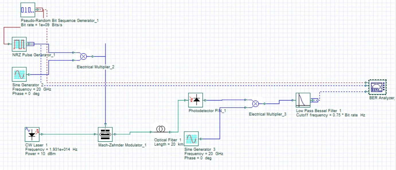 Scheme to obtain a RoF signal with sidebands.
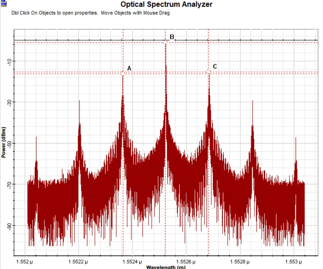 Sidebands for nm and RF of GHz. Point A marks nm, point B nm, and point C nm.
Single-sideband generation
In an optical modulation system using a Mach-Zehnder modulator (MZM), it is possible to suppress one of the sidebands generated during modulation. This is done by introducing a specific phase shift in one of the MZM’s arms, normally set to or radians.
The MZM operates on the interference of two optical waves traveling through its two arms. Applying an RF signal to the modulator changes the refractive index in one or both arms, which produces a phase change in the light passing through them. When the light waves recombine at the MZM output, the resulting interference pattern varies in time, following the RF signal — which is equivalent to modulating the amplitude of the optical carrier.
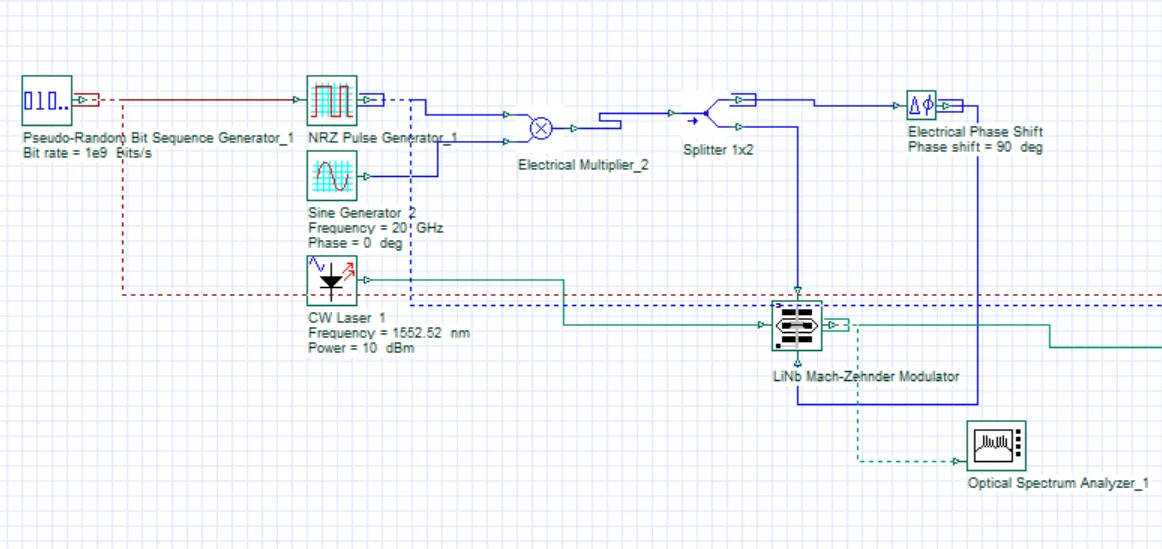 OptiSystem scheme to obtain a single sideband.
In the scheme above, we phase-shift one of the input arms of the Mach-Zehnder modulator by . Opening the optical spectrum analyzer, we see that the sideband at nm is attenuated in amplitude, while the optical carrier and the other sideband are barely affected.
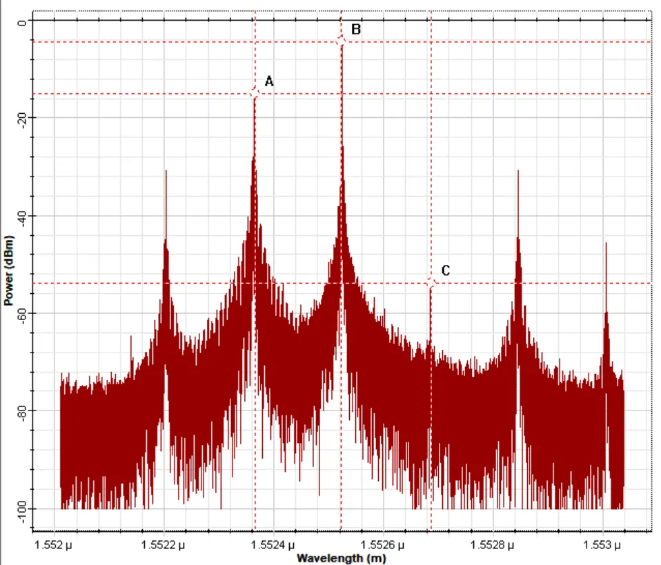 Optical spectrum analyzer for the single-sideband case.
Demodulation
In a RoF system, after the optical signal has been converted to an electrical signal by the photodetector, a demodulation step is essential to recover the original RF signal. For this we use a sine-pulse generator at the same frequency as the RF signal used in the modulation stage at the start of the system.
The reason for using a sine generator at the same frequency lies in the demodulation method — commonly known as mixing or homodyne detection. The electrical signal from the photodetector, which carries the modulated RF information, is mixed with a locally generated reference signal of the same frequency as the original RF signal. Mixing the two produces constructive and destructive interference that extracts the modulated RF information.
The precision of the sine generator’s frequency is crucial for successful demodulation. If it does not match the original RF frequency exactly, the interference is not optimal, leading to inefficient recovery of the information and a degraded demodulated signal. In the eye diagram, large differences appear if we use frequencies that do not match exactly — that is, the demodulation will not match the originally transmitted signal.
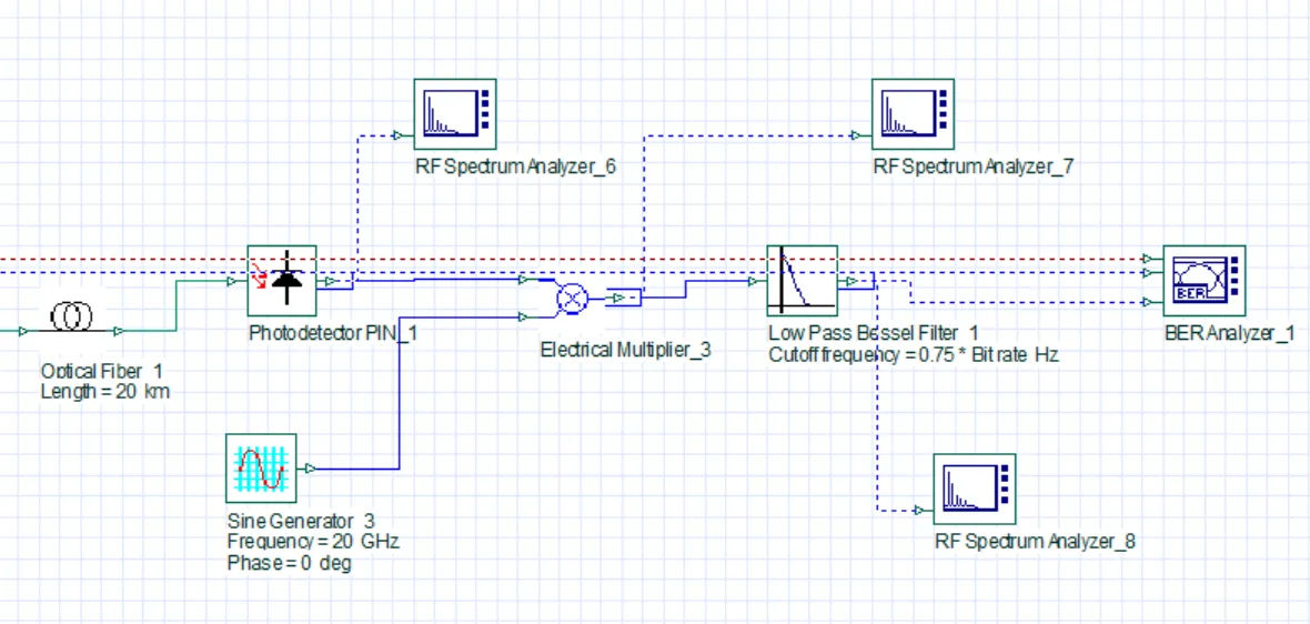 Continuation of the previous scheme, showing the electrical pulse used for demodulation.
The figure above shows the components used for demodulation for a single-channel system. The low-pass filter lets us ignore the higher frequencies, leaving only the envelope of the signal. Finally, we compare the demodulated signal against the originally transmitted signal through the eye diagram.
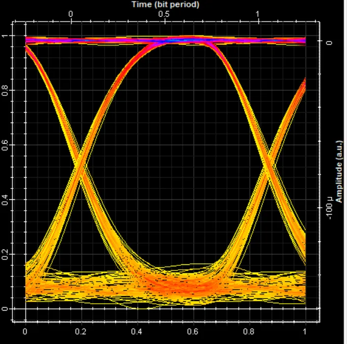 BER analyzer for the single-channel system.
The complete 3-channel system
To build the 3-channel system we multiplex three blocks like the single-channel one above. At the multiplexer output we then expect three optical carriers, each with two sidebands — one of which has already been attenuated, so in power terms it can be ignored. The full-system scheme includes signal generation, filters to attenuate the optical carriers, and finally demodulation of the electrical signal.
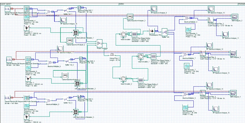 Schematic for the complete 3-channel system.
Two-channel system
As a test, I started with a two-channel system. For both channels the eye diagram is shown to confirm that the signal is being demodulated correctly.
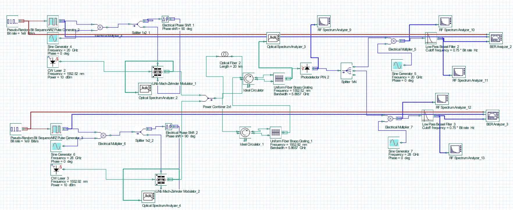 Scheme for a two-channel system. Both channels use single-sideband modulation and passive filtering to attenuate the optical carriers.
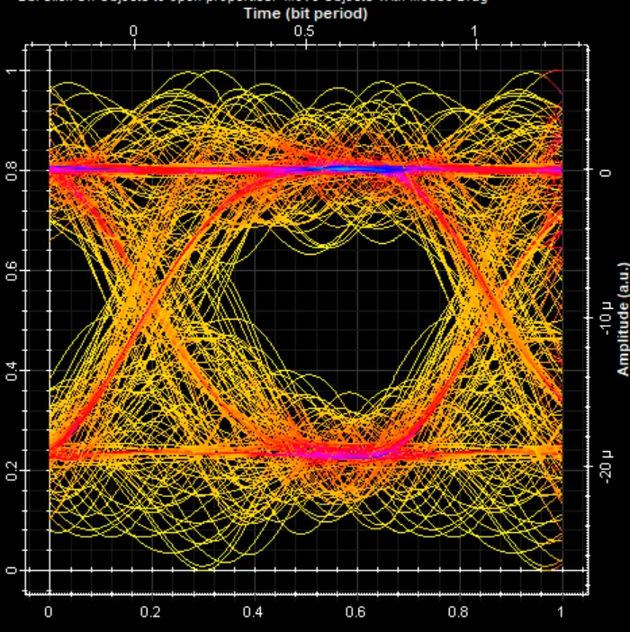 Two-channel system: eye diagram for the first channel.
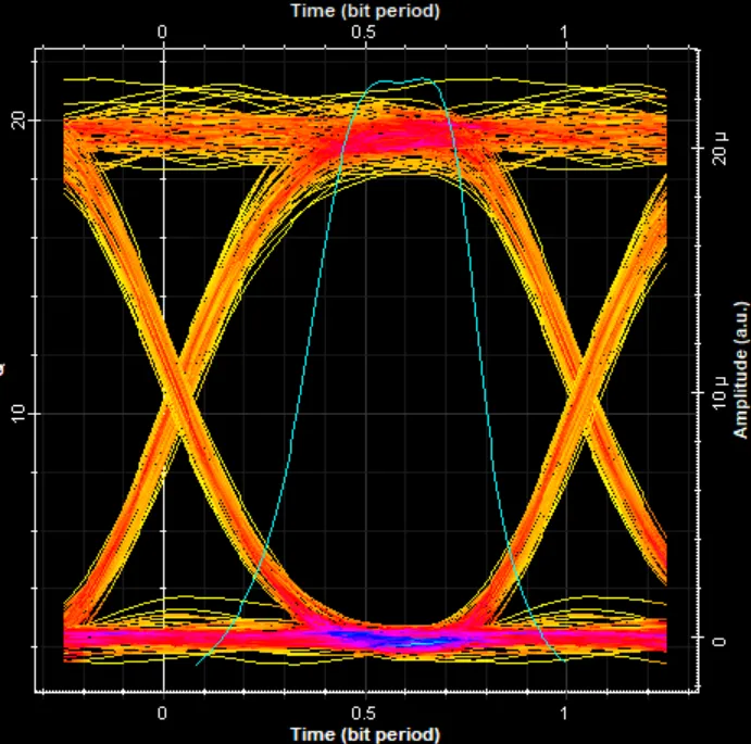 Two-channel system: eye diagram for the second channel.
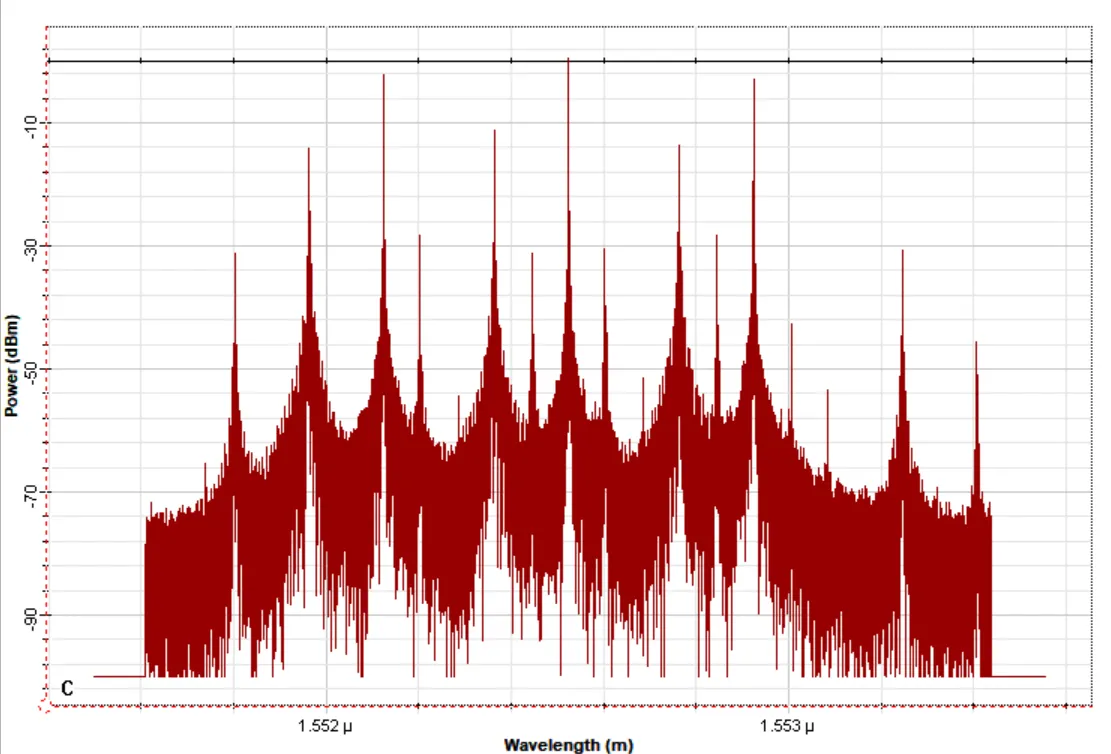 Spectrum at the multiplexer output for the 3-channel system.
Three-channel system
Signal parameters:
- Channel 1: CW laser nm, sine generator frequency GHz.
- Channel 2: CW laser nm, sine generator frequency GHz.
- Channel 3: CW laser nm, sine generator frequency GHz.
Layout parameters:
- Bit rate: bits/s
- Sequence length: bits
- Samples per bit:
- Number of samples:
The eye diagrams for the complete system are shown below. At first I thought there might be high-power electrical frequencies not being captured by the layout properties, but after increasing that range there was no appreciable change, so the source of error must come from elsewhere. Comparing against the two-channel results suggests that a many-channel implementation would require more aggressive filtering.
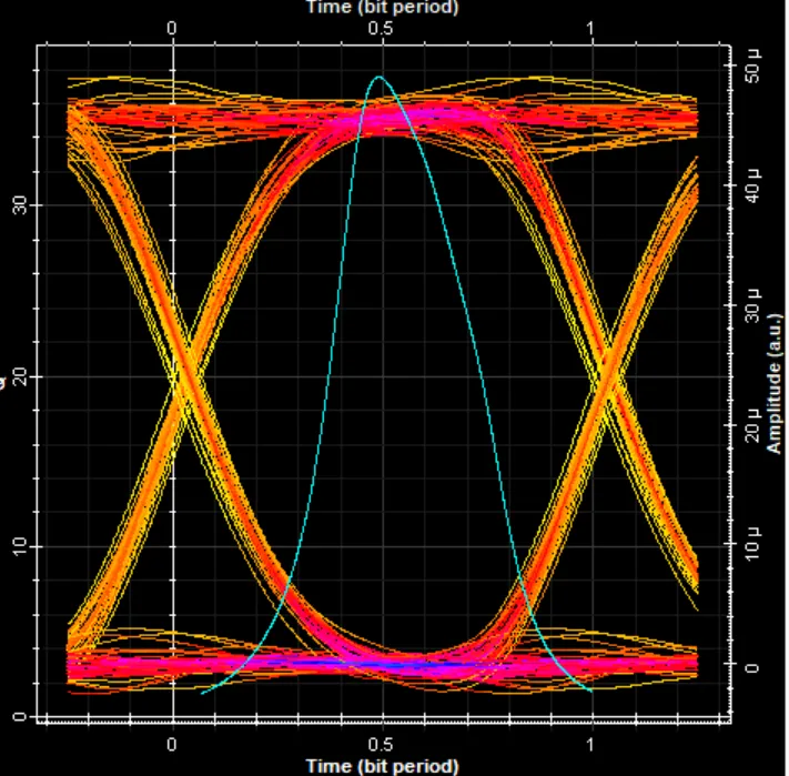 Eye diagram for the optical carrier nm and RF carrier of GHz.
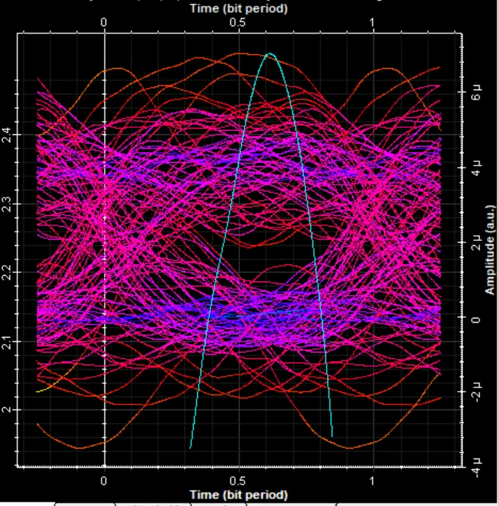 Eye diagram for the optical carrier nm and RF carrier of GHz.
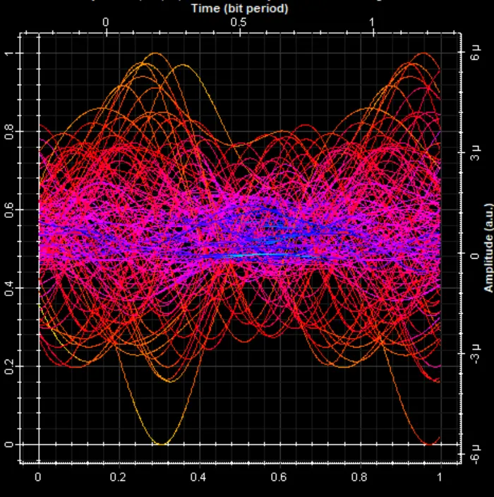 Eye diagram for the optical carrier nm and RF carrier of GHz.
Other implementation ideas
A more optimal way to send the signal would be to make better use of the bandwidth — i.e., shift the RF carriers to the left so they end up within the range while leaving the optical carriers intact. Any overlapping between the RF carriers would have to be accounted for, so that the highest-power frequencies are not too close together and the signal can still be demodulated correctly.
Reducing the CSR (carrier-to-sideband ratio)
The following is in the context of the 3-channel system.
Fiber Bragg gratings (FBGs) work by selectively reflecting certain wavelengths and letting others pass. This is achieved by creating a periodic pattern of refractive-index variations in the core of the optical fiber.
In a RoF system where a Mach-Zehnder modulator generates amplitude-modulated signals, FBGs can be used to effectively filter one side of the band (upper or lower) near the optical carrier. This reduces the CSR by attenuating or eliminating one of the sidebands, while the other sideband — which carries the information — is preserved.
 FBGs chained together, each centered near one of the optical carrier frequencies.
Before the FBGs, the power difference between the sidebands and the carrier is about dBm. Once the signal passes through them, that difference is reduced to dBm.
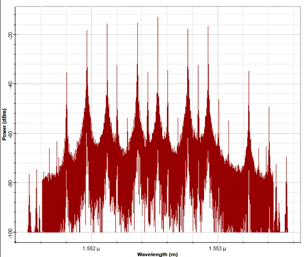 Frequency spectrum after the signal passes through the FBG chain.